transistor-to-transistor logic (TTL)
What is transistor-to-transistor logic (TTL)?
Transistor-to-transistor logic -- also known as simply transistor-transistor logic or TTL -- is a family of digital logic design built from a family of bipolar junction transistors that act on direct-current pulses. Many TTL logic gates are fabricated onto a single integrated circuit (IC). TTL ICs usually have four-digit numbers beginning with 74 or 54.
TTL technology was invented in 1961 by James L. Buie, and Sylvania released the first commercial TTL ICs in 1963. Three years later, Texas Instruments introduced its 7400 logic family of TTL IC devices, providing electronics designers with a set of building blocks for creating the complex digital logic circuit used in a range of devices, including early computers. TTL devices from the 7400 family served as glue logic between complex ICs as components evolved and diversified over the next several decades.
TTL technology and the 7400 family have been largely obsolete since the 1990s, replaced by complementary metal oxide silicon and other low-power, high-density and high-speed IC technologies. However, the fundamental logic gates -- such as AND, OR, NAND and NOR gates -- embodied in TTL ICs remain essential logical constructs and are incorporated into digital logic circuitry fabricated onto very large-scale integration (VLSI) IC microprocessors to this day. For example, flash memory devices such as thumb drives and solid-state drives are built on the concepts of NAND gates and NOR gates common in classic TTL ICs.
How does TTL work?
TTL gates are designed using at least two transistors and supporting components, including resistors and diodes. Each component serves specific purposes:
- Transistors provide switching, turning on or off in response to input signals.
- Resistors limit current and help optimize voltage levels for the transistors.
- Diodes ensure current flows in only one direction, helping to stabilize the circuit.

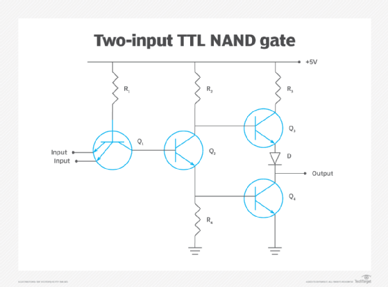
Figure 1 illustrates a basic two-input TTL NAND gate schematic. Transistor Q1 is the input transistor. Inputs, such as A and B, feed the emitter of Q1. Transistor Q2 serves as a phase splitter, and transistors Q3 and Q4 create a totem pole output that provides high stability and a high fan-out capability for the output.
When inputs A and B are on -- logic 1 or high -- transistors Q2 and Q3 turn on and act as amplifiers, while transistor Q4 turns on to create a logic 0 or low logic output. When either or both inputs A and B are off -- logic 0 or low -- transistors Q2 and Q4 turn off to create a logic 1 or high logic output.

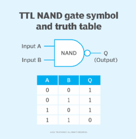
The logical representation of this NAND gate circuit is shown in Figure 2.
Other logic gates will use slightly different circuit configurations to achieve each respective logical behavior -- such as AND, OR and NOR -- but the overall concept is similar.
Characteristics and considerations of TTL
TTL gate circuits and the IC packages that hold the gates involve important characteristics that designers consider in their digital circuit designs. While TTL components are no longer widely used in commercial digital circuit design, the fundamental characteristics remain important for VLSI components, such as an application-specific integrated circuit (ASIC), processor and other complex digital components used in modern electronic devices.
These characteristics include the following:
- Fan-in. This is the number of inputs connected to a gate or the number of inputs a TTL gate can handle.
- Fan-out. This is the number of outputs a TTL gate can drive or operate without affecting the gate's performance. This is typically 10 loads from other TTL gates.
- Power dissipation. This is the amount of power the gate or device will use. It's taken as the product of supply voltage, measured in volts, multiplied by the current drawn, measured in amperes, and is typically measured in milliwatts (mW). Power dissipation for a typical TTL gate is about 10 mW.
- Propagation delay. This is the time needed for the gate's output to change in response to a change in the gate's inputs. This is an expression of latency, and it limits the overall digital circuit's top speed. Propagation delay is measured in nanoseconds (ns). The delay for a typical TTL gate is about 10 ns.
- Noise margin. Digital signals aren't perfect; noise margin is the voltage range allowed for the input signal voltage that won't affect the output logic level. Standard TTL gates allow a noise margin of about 0.4 volts.
- Temperature range. This is the range of safe operating temperatures allowed for the gate. Standard 7400 family TTL gates have a temperature range from 0 to 70 degrees Celsius; 5400 family gates have an extended range of minus 55 to 125 degrees Celsius.
- Special characteristics. Some TTL gate products were fabricated for high reliability and radiation resistance for military and aerospace uses.
Types of TTL
TTL circuit designs evolved and diversified over decades of use to optimize certain characteristics such as speed, power consumption and output power to drive other components. The most popular types of TTL include the following:
- Standard TTL represents the traditional 7400 family of components with standard characteristics, including a typical power dissipation of 10 mW per gate and a propagation delay of 10 ns per gate.
- Fast TTL trades faster switching speeds for higher power consumption. For example, a fast TTL gate might switch in 6 ns but use 22 mW. This is sometimes called high-power TTL.
- Low-power TTL trades lower power consumption for slower switching speeds. For example, a low-power TTL gate might use 1 mW but have a delay of up to 33 ns.
- Low-voltage TTL uses a 3.3 volts direct current supply voltage instead of the usual 5 VDC supply voltage, resulting in only about 2 mW of power per gate. The lower supply voltage will lower power dissipation per gate and can help speed propagation delays because the difference in logic 0 and logic 1 voltage levels is smaller.
- Schottky TTL includes Schottky diode clamps in the TTL gate, which accelerates gate switching time to about 3 ns. However, this increases power use to about 19 mW per gate.
- Low-power Schottky TTL, also called advanced Schottky TTL, combines low-power TTL and Schottky diodes to offer a fast 9.5 ns propagation delay and 2 mW of power use per gate.
- Open-collector TTL leaves the output transistor's collector lead open and effectively unpowered from the chip's supply voltage, allowing designers to incorporate high-voltage or grouped outputs to drive non-TTL loads. Examples of open-collector TTL ICs include the traditional 7401 and 7403.
- Tri-state TTL, sometimes called three-state TTL, includes additional circuitry that lets the gate be disconnected. It's often used in the design of bus TTL circuitry where numerous gates might be present on the same wire. The third disconnected state creates a high-impedance state that isolates or disconnects the gate and prevents it from interfering with other gates using the common bus connections.
Applications of TTL
TTL was the standard for digital electronic circuit design from its inception in the 1960s through the 1980s. At that time, the broad adoption of highly integrated, custom-fabricated digital components such as VLSI and ASIC chips displaced the chips with individual gates.
TTL was embraced for its advantages, such as low cost, solid noise margin for stable and reliable logic signal levels, ample fan-out to drive subsequent TTL gates, and modest power dissipation to keep circuits cooler and more energy-efficient.
However, TTL was relatively slow, and circuits composed of many gates were power-hungry. Even though individual gate delays measured just a few nanoseconds, the need to construct large, complex circuits from many gates and chips made the propagation delays cumulative, limiting the overall circuit's top speed. The printed wiring needed to interconnect the gates in each chip added to the latency and made large circuits vulnerable to electrical signal noise. As a result, TTL wasn't a good choice for high-performance circuits, such as early processors.
TTL saw most of its service in controller-type digital circuits, including simple controllers, basic computer interface designs such as early storage interface controllers for floppy disks and early magnetic hard drives, and dedicated circuits for industrial electronic systems. It wasn't until the logic functions of TTL gates were integrated into high-density chips such as VLSI and ASIC devices that digital electronics exploded into commercial and consumer applications.
TTL vs. emitter-coupled logic
Emitter-coupled logic (ECL) is an alternative electronic circuit design used in the construction of digital logic gates. Compared with TTL construction, ECL construction uses an overdriven bipolar transistor differential amplifier and limited emitter current to prevent saturating the transistors and turning them fully on. ECL is often referred to as current-steering logic, because current is steered between the emitter-coupled transistor pair.
ECL became a notable alternative gate design; its unsaturated transistors can be switched much faster, and with far lower propagation delay, than TTL gate designs. ECL gates demonstrate a typical propagation delay of 1 to 2 ns compared with about 10 ns for a standard TTL gate. ECL fan-out is also much higher at about 25 gate loads compared with a TTL fan-out of about 10, allowing ECL gates to drive more digital devices.
The main disadvantage of ECL is its much higher power dissipation than TTL. In addition, the low voltage difference between logic 0 and logic 1 leaves ECL gates with poor noise immunity. These two factors limit ECL circuit complexity and use cases.
TTL provided the foundation for today's logic gates and digital circuitry. Find out more about various kinds of logic gates and how they work.
