What are logic gates?
A logic gate is a device that acts as a building block for digital circuits. Logic gates perform basic logical functions fundamental to digital circuits. Most electronic devices we use today have some form of logic gate in them.
Logic gates can be used, for example, in digital electronics such as smartphones and tablets or in memory devices. Commonly used in integrated circuits (IC), logic gates are also crucial building blocks for electrical and electronic components like counters, processors, resistors, transistors and diodes.
How do logic gates work?
In a circuit, a logic gate works based on a combination of digital signals from its inputs. Most logic gates have two inputs and one output. Applying Boolean algebra, the gate performs some logical operation on the inputs to make a decision and produce a single binary output. At any moment, every terminal is in one of the two binary conditions: true (high) or false (low). False is represented as 0 and true as 1.
Think of a logic gate like a light switch, where in one position, the output is off (0), and another, it's on (1). Depending on the type of logic gate used and the combination of inputs, the binary output will differ. In an AND gate, the output will be 1 if both its inputs are 1. An OR gate will produce an output of 1 if only one of the inputs is 1. Combining multiple logical gates in an IC can create different combinations of outputs for different combinations of inputs.
Basic logic gates
There are seven basic logic gates: AND, OR, XOR, NOT, NAND, NOR and XNOR.
AND gate
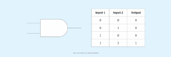
The AND gate produces an output of true only when both inputs are true. Otherwise, the output is false. In other words, the output is 1 only when both inputs are 1, and 0 if even one of the inputs is 0. The gate is named so because, if 0 is false and 1 is true, the gate acts in the same way as the logical and operator. Figure 1 provides a truth table showing the circuit symbol and logic combinations for an AND gate. In the symbol, the input terminals are on the left, and the output terminal is on the right.
OR gate
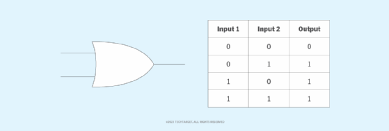
In the OR gate, which is among the most widely used logic circuits in digital devices and components, the output is true if one or both inputs are true. If both inputs are false, the output is false. For the output to be 1, at least one input must be 1. The gate gets its name from behaving like the logical inclusive or. Figure 2 shows a truth table for the OR gate.
XOR gate
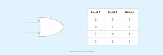
The XOR, or exclusive OR, gate acts in the same way as the logical either/or. The output is true if either input is true, but not both. The output is false if both inputs are false or both inputs are true. Similarly, the output is 1 (true or high) if the inputs are different, but 0 (false or low) if the inputs are the same. Figure 3 shows a truth table for a 2-input XOR gate.
NOT gate
A logical inverter, sometimes called a NOT gate to differentiate it from other types of electronic inverter devices, has only one input. A NOT gate reverses the logic state. If the gate's input is 1, then the output is 0. If the input is 0, the output is 1. One of the only logic gates that accepts a single input and produces a single output, the NOT gate is also one of the simplest since all it does is reverse the input applied. As shown in Figure 4, a truth table for a NOT gate is simple.

NAND gate
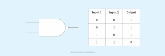
The negated AND, or NAND, gate operates as an AND gate followed by a NOT gate. Its symbol is an AND gate with the circle of a NOT gate at the output. The NAND gate produces a false or low output if both inputs are true. Otherwise, the output is true. Another way to visualize it is that a NAND gate inverts the output of an AND gate. It acts in the manner of the logical operator and followed by negation. Figure 5 provides a truth table showing the logic of a NAND gate for two types of inputs.
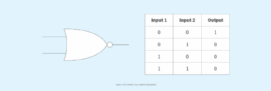
NOR gate
The NOR, or NOT OR, gate is a combination OR gate followed by an inverter. Its output is true or high if both inputs are false or low (logic 0). Otherwise, the output is false. This logic is easy to understand with the gate's truth table, shown in Figure 6.
XNOR gate
The XNOR, or exclusive NOR, gate is a combination of an XOR gate followed by an inverter. Its output is true if the inputs are the same and false if the inputs are different. It produces a true output, regardless of whether the inputs are true or false. However, they must both be the same for the output to be true. The XNOR truth table looks like Figure 7.

Universal logic gates
The NAND and NOR gates are known as universal logic gates since they can be implemented in digital circuits to perform any Boolean function without additional logic gates. These gates can also replicate the functionality and behavior of the other gates. In doing so, they help to simplify the design -- and often the cost -- of digital ICs.
For example, two NAND gates can be used to create an AND gate. In this case, the first NAND gate will inverse the logical AND operation of the two inputs. The second NAND gate then inverts this output to produce the original AND logic. Similarly, three NAND gates can be used to create an OR gate. The first NAND gate will inverse the first input, the second will inverse the output of the first NAND gate, and the third NAND gate will produce the logical OR of the outputs of the first two NAND gates.
NAND gates can also be used to simulate the outputs of XOR, NOR and XNOR gates. Similarly, the NOR logic gate can be used to replicate the output of all these logic gates:
- AND gate.
- OR gate.
- NAND gate.
- XNOR gate.
- XOR gate.
Composition of logic gates
High or low binary conditions are represented by different voltage levels. The logic state of a terminal can, and generally does, change as the circuit processes data. In most logic gates, the low state is approximately 0 volts, while the high state is approximately +5 V.
Logic gates can be made of resistors, transistors or diodes. These components are wired together in specific configurations to ensure they transform the inputs in expected ways. Resistors, for example, can commonly be used as a pull-up or pull-down resistor. Pull-up and pull-down resistors are used when there are any unused logic gate inputs to connect to a logic level 1 or 0. This prevents any false switching of the gate.
Likewise, transistors provide switching -- turning on or off in response to input signals -- while diodes ensure current flows in only one direction to stabilize the circuit.
Commonly used logic gates are transistor-to-transistor logic (TTL) and complementary metal-oxide-semiconductor (CMOS). TTL ICs use negative-positive-negative and positive-negative-positive bipolar junction transistors. CMOS ICs are constructed from metal-oxide-semiconductor or junction field-effect transistors. TTL ICs might commonly be labeled as the 7400 series of chips, while CMOS ICs might often be marked as a 4000 series of chips.
Learn about fan-out in digital circuitry, a measure of the maximum number of digital inputs the output of a single logic gate can feed without disrupting circuitry operation.
Why are logic gates needed?
Logic gates perform basic logical functions that all digital operations rely on, regardless of device type. These functions occur at high speeds, enabling fast data processing and transfer in electronic devices.
Logic gates are also crucial for devices running low-power-consumption applications. This is because the gates consume little power and require little energy.
Combining logic gates in various configurations helps create more complex ICs. In theory, there's no limit to how many gates can be arrayed together in a single device. But in practice, the number of gates that can be packed into a given physical space is limited. Recent and ongoing developments in computing and electronics engineering are changing this, accommodating ICs and devices with more gates placed in ever-decreasing spaces in increasingly complex devices.
Where are logic gates used in real life?
Arrays of logic gates are found in digital ICs. These ICs appear in a wide, growing range of digital devices, including laptops, tablets, smartphones, memory devices, digital clocks and televisions. As IC technology advances, the physical volume required for individual logic gates decreases, and digital devices can perform more complicated operations faster.
Quantum computers also have their own version of logic gates, called quantum logic gates or qutrit quantum gates. These quantum circuits operate using a small number of qutrits, which are qubits -- quantum bits -- that have one added dimension. Just as logic gates are the building blocks of digital circuits, qutrit quantum gates are foundational to quantum circuits.
Quantum computing development can significantly enhance data center operations. Potential applications of quantum computing include optimizing supply chains, improving financial modeling, and enhancing AI and machine learning capabilities. Explore future potential quantum computing uses.