What is NRZ (non-return-to-zero)?
NRZ (non-return-to-zero) is a form of digital data transmission in which the binary low and high states, represented by numerals 0 and 1, are transmitted by specific and constant direct current (DC) voltages.
What are RZ and NRZ?
Both return-to-zero (RZ) and NRZ are modulation techniques or bitstream encoding schemes used in telecommunications to encode data.
RZ is a binary encoding scheme in which the signal returns to 0 volts (V) between pulses or data bits, even if there are multiple consecutive zeros or ones in the signal. Thus, the signal has three valid levels: high, low and zero. Here, the zero between each low or high bit is a neutral or rest condition. In contrast, NRZ uses only two voltage levels (high and low) and no rest (zero) condition.
The use of non in NRZ is somewhat unintuitive, considering that one of the logic states might be represented by zero voltage. However, this confusion becomes clear from the comparative definition of NRZ to RZ.
One key feature of the RZ scheme is that the signal is self-clocking, meaning synchronization information is embedded within it. A separate clock does not have to be sent with the signal to enable its decoding. Another advantage of RZ encoding is that RZ signals have better receiver sensitivity than NRZ signals at even or lower transmitted power. Conversely, the scheme uses twice the bandwidth of NRZ to achieve the same data rate.
In NRZ encoding, the signal is not self-clocking. Thus, a separate source of synchronization is needed to decode the signal and to avoid bit slips. Another issue is that continuous identical voltage levels can make clock recovery difficult, hindering the receiver from maintaining synchronization with the transmitter's clock. The main advantage of NRZ encoding is that it offers higher bandwidth utilization and its pulses have more energy. As a result, NRZ is more suitable for high-speed data transmission than RZ encoding.

How does NRZ work?
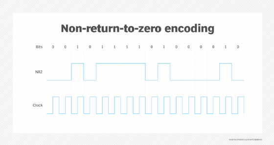
In NRZ, two voltage levels are used: One level represents logic 0, and the other represents logic 1. Usually, the positive voltage represents or corresponds to ones, while the negative voltage represents or corresponds to zeros. There is no neutral or rest condition in NRZ, and no signal changes are introduced between bits.
NRZ simplifies data transmission and makes it easy to interpret digital information because distinct voltage levels are maintained for different logic states. Additionally, the voltage state of each bit remains constant within a clock period. Thus, if the state is one, it remains at that level (high), whereas, if it is zero, it remains at the low level.
Positive-logic NRZ vs. negative-logic NRZ
In positive-logic NRZ, the low state is represented by the more negative or less positive voltage, and the high state is represented by the less negative or more positive voltage. Here are two examples:
Logic 0 = +0.5 V
Logic 1 = +5.0 V
Logic 0 = -3.0 V
Logic 1 = 0.0 V
In negative-logic NRZ, the low state is represented by the more positive or less negative voltage, and the high state is represented by the less positive or more negative voltage. Here are two more examples:
Logic 0 = +5.0 V
Logic 1 = +0.5 V
Logic 0 = 0.0 V
Logic 1 = -3.0 V
Benefits and drawbacks of NRZ
NRZ provides a simple, uncomplicated technique to encode data in digital communications systems. It's easy to understand and implement since it utilizes only two signal levels. Its simplicity also reduces system implementation cost.
One key property of NRZ is that each bit maintains the same voltage state. This simplifies signal detection and decoding. A consistent signal also minimizes signal distortion over long distances, making NRZ suitable for long-distance data transmission. Also, since there are fewer signal transitions, bandwidth utilization is high, making NRZ ideal for applications requiring high-speed data transmission.
A well-known drawback of NRZ is clock signal desynchronization due to continuous identical voltage levels and the absence of a self-clocking encoding method. Continuous voltage levels can also introduce a DC component into the signal, affecting the receiver's ability to accurately decode it. The presence of low-frequency components can also distort or attenuate the signal. Additional devices, such as amplifiers or repeaters, may be required to mitigate these issues, which can increase the signaling system's complexity and cost.
Applications of NRZ
The simplicity of NRZ is particularly suited for short-distance, high-speed data transmission applications, like local area networks and data centers. NRZ is also commonly used to achieve higher Ethernet speeds (200/400 Gigabit Ethernet) and for network communication.
NRZ has several other applications:
- Facilitating data input and output in storage devices, like hard disk drives.
- Converting data into digital audio or video signals suitable for transmission.
- Transmitting sensor and control data in industrial settings.
- Supporting data communication protocols.
- Sending data in satellite communications.
NRZ vs. PAM
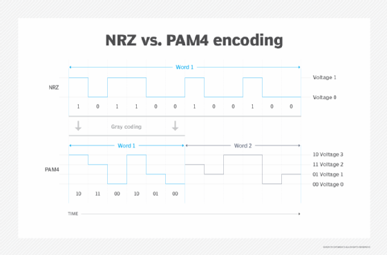
NRZ is also known as 2-level pulse amplitude modulation (PAM-2). Since it uses low and high voltage (signal) levels to represent logic 0 and logic 1, it can transmit only one bit of information per signal symbol period. This bit can be either zero or one but not both.
In contrast, PAM-4 is a multilevel signal modulation technique. With this method, a signal level can represent two bits of logic information, and four voltage levels are used to represent four combinations of the two-bit logic: 00, 01, 11 and 10. Thus, in PAM-4, each clock cycle can be sent with voltages of 0, 1, 2 or 3. These voltages respectively correspond to 00, 01, 11 and 10.
One of the chief advantages of PAM-4 is that it can pull twice the signal compared to NRZ. Also, it has a throughput of two bits per unit interval, which is twice the throughput of NRZ for the same baud rate -- the rate at which a symbol can change. For NRZ, the baud rate, also known as the symbol rate, equals the bit rate because each symbol contains only one bit. So, a bit rate of 28 gigabits per second is similar to a baud rate of 28 gigabauds per second. In contrast, PAM-4 doubles the bit rate for a given baud rate since it transmits two bits per symbol, making it more efficient for high-speed optical transmission than NRZ.
Since PAM-4 has only half the baud rate as NRZ, it can transmit twice as much data per symbol cycle and ensure a significantly lower signal loss in the channel. As a result, existing channels can be used without the need to increase -- e.g., double -- the baud rate or channel loss. This is another crucial advantage of PAM-4 over NRZ.
Also, PAM-4 has half the Nyquist frequency of NRZ. This feature doubles the data density available and generates a higher resolution for the same oversampling rate. Since NRZ has a higher Nyquist frequency, it experiences higher channel-dependent loss.

One big drawback of PAM-4 is that its signal-to-noise ratio is -9.54 decibels, which is significantly worse than SNR for NRZ (0 dB). High SNR adversely affects signal quality in PAM-4. PAM-4 also has a substantial reflections problem -- three times worse than NRZ -- has a higher bit error rate and requires more expensive equipment.
PAM-4 transceivers also produce more heat, since more power is used than the NRZ link. However, this particular drawback can be mitigated by applying silicon photonics to transceivers to reduce their energy consumption.
Learn about synchronous vs. asynchronous communications, networking vs. telecommunications, different types of networks and their use cases, and common network protocols and their functions.
