G-code
What is G-code?
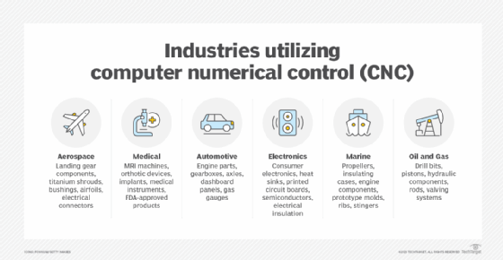
G-code, also known as geometric code or RS-274, is the most prevalent programming language for computer numerical control (CNC) machines used in computer-aided design and computer-aided manufacturing (CAD/CAM). G-code commands provide what-, which- and how-type instructions to the machine, such as what to do, how to do it, where to move, which path to follow, etc.
What is the importance of G-code?
G-codes for CNC machines are universal, meaning all CNC machines need G-code to function and carry out specific operations. Since the code layer is meant for machines to understand, it is usually hidden from human users, although the commands themselves are readable by humans. CAD/CAM software automatically generates G-code programs depending on the application, so a dedicated programmer is usually not required. The exception is when complex or customized parts need to be built and require specific code changes that cannot be done automatically by the software.
G-code commands tell the computer that controls the motors of the manufacturing equipment how far to move and at what speed. A mill has a spinning tip that carves a metal block, for example, into an intricately machined part. G-code can provide the instructions to the computer-controlled equipment to move the head through 3D maneuvers at differing speeds to create a camshaft, which, as an example, might be used to control valve timing in a gasoline-powered engine.

What is G-code used for?
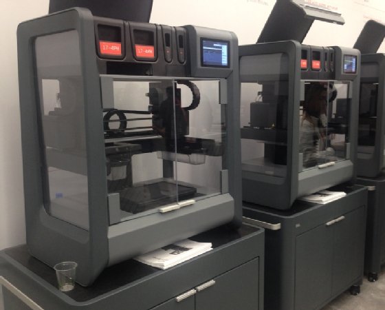
G-code provides metric-based numeric control of CAM-controlled equipment such as CNC milling machines and for additive manufacturing applications, such as 3D printing. G-code commands provide the precise and repeatable paths that are needed to position or move machines as well as get them to perform specific actions, such as cutting or shaping. The machine's controller converts the G-code commands into specific instructions that the machine can understand and act on. In general, the fine-grained control enabled by G-code and other CNC languages affords the precision for additive and reduction-based fabricating using many materials.
For example, in manufacturing, G-code commands instruct lathes, mills and other machines to follow a specific process to produce a desired product from the given raw materials. Similarly, 3D printers need G-code commands to create the various layers that constitute a product's specific design and shape.
Some of the applications of G-code are the following:
- Three-axis mills.
- Four- or five-axis machining centers.
- Lathes.
- Cutters.
- Wire cutters.
- Jig borers.
- Drills.
- Printheads.
- 3D printers.

What are the three basic G-codes?
G-code commands follow a very simple structure: the letter G followed by two numbers. Although there are many G-code commands, three common commands are G00, G01 and G02.
The G00, or Rapid Positioning, command moves the machine at maximum speed from a current position to a specified point. With this command, all the axes move together, resulting in a straight line movement to the new position. After the movement, some other job, such as cutting or printing, can be initiated.
The G01, or Linear Interpolation, command instructs the machine to move in a straight line at a set Speed F to an end position, which is specified with (x,y,z) values. As the machine moves, its controller calculates all intermediate points until it reaches position F.
The G02, or Circular Interpolation, command instructs the machine to move clockwise in a circular pattern. Like the G01 command, the G02 command requires the end point parameters to be defined plus the center of rotation.
The three commands can be used sequentially to provide different instructions to the machine. First, G00 might be used to move the machine to the desired position, followed by G01 to cut or extrude material and G02 to perform another machining process.
Some other G-code commands include the following:
- G03, or Circular Interpolation Counter-clockwise. It instructs the machine to move counter-clockwise in a circular pattern.
- G20. It define the G-code units in inches.
- G21. It defines the G-code units in millimeters.
- G17, G18, and G19. Instructions to set the machine's working plane coordinates, which are (XY/XZ/YZ).
- G28. It instructs the machine to move to its reference point or home position.
G-code commands are also available to interpret coordinates and position the tool, specify dwell time, set up cutter compensation, set spindle speeds, configure coolant flows, initiate scaling, and control tool changes.
Many G-code commands are modal, meaning they will remain in effect and actioned by the CNC machine until they are replaced by another code or canceled.
History of G-code
In the early days of machining, tools were controlled by cards or punch tape, created by punching holes into the cards or tape. However, physical damage to the paper material often resulted in errors. The development of computers for operating numerical-controlled tools led to the development of computer numerical control machines.
The first numerical computer control language was developed by MIT in the late 1950s. The earliest version of G-Code was standardized by the Electronic Industries Alliance in the early 1960s. It eventually became the standardized RS-274D language that is used by many CNC machines and applications.
Over the years, multiple versions of the G-code standard have emerged, many tailored to a machine manufacturer's own equipment. Today, the exact, reproducible manufacturing afforded by G-code and similar languages is used in the creation of all kinds of military and scientific equipment and consumer goods.
G-code and M-code
G-codes and M-codes often work together in tandem. Like G-code commands, M-code commands also have specific applications, so both are used, depending on what the tool is required to do.
M-code, which stands for machine code or miscellaneous code, refers to commands that control the machine's miscellaneous functions. The structure of M-code commands is as simple as the structure of G-code commands with one difference: Each command starts with an M.
Some commonly used M-code commands are the following:
- M00. Program stop.
- M02 and M30. End of program
- M05. Spindle stop.
- M06. Tool change
- M106. Set fan speed. Used for 3D printing.
The processes of additive and subtractive manufacturing are distinct yet connected at the same time. Discover the key differences between these two manufacturing approaches.
