Identifying issues in a multi-site Cisco UC deployment
Deploying Cisco Unified Communications Manager between multiple sites requires an appropriate dial plan, appropriate bandwidth, a quality of service (QoS) implementation and a design that can survive IP WAN failures. This chapter will explain the issues that can arise in a multisite Cisco UC Manager deployment, and recommend specific solutions.
Download and read "Identifying Issues in a Multisite Deployment" in its entirety.
Implementing Cisco Unified Communications, Part 2
Chapter 1, Identifying Issues in a Multisite Deployment
 |
|
Deploying Cisco Unified Communications Manager between multiple sites requires an appropriate dial plan, appropriate bandwidth, a quality of service (QoS) implementation and a design that can survive IP WAN failures.
This chapter will explain the issues that can arise in a multisite Cisco UC Manager deployment, and recommend specific solutions.

Identifying Issues in a Multisite Deployment
Table of contents:
1. Multisite deployment challenge overview
2. Quality challenges
3. Bandwidth challenges
4. Availability challenges
5. Dial plan challenges
6. Overlapping and nonconsecutive numbers
7. Fixed versus variable-length numbering plans
8. Variable-length numbering, E.164 addressing and DID
9. Optimized call routing and PSTN backup
10. NAT and security issues

Multisite deployment challenge overview
Formerly known as Cisco Call Manager (CCM), Cisco Unified Communications Manager (CUCM) multi-site deployment challenges can include the following:
-
Quality issues: Real-time communications of voice and video must be prioritized over a packet-switching network. All traffic is treated equally by default in routers and switches. Voice and video are delay-sensitive packets that need to be given priority to avoid delay and jitter (variable delay), which would result in decreased voice quality.
-
Bandwidth issues: Cisco Unified Communications (Cisco UC) can include voice and video streams, signaling traffic, management traffic, and application traffic such as rich media conferencing. The additional bandwidth that is required when deploying a Cisco Unified Communications solution has to be calculated and provisioned for to ensure that data applications and Cisco Unified Communications applications do not overload the available bandwidth. Bandwidth reservations can be made to applications through QoS deployment.
-
Availability issues: When deploying Cisco Unified Communications Manager (CUCM) with centralized call processing, IP Phones register with CUCM over the IP LAN and potentially over the WAN. If gateways in remote sites are using Media Gateway Control Protocol (MGCP) as a signaling protocol, they also depend on the availability of CUCM acting as an MGCP call agent. It is important to implement fallback solutions for IP Phones and gateways in scenarios in which the connection to the CUCM servers is broken because of IP WAN failure. Fallback solutions also apply to H.323 gateways but are already created with H.323 dial peers in a proper H.323 gateway configuration.
-
Dial plan issues: Directory numbers (DN) can overlap across multiple sites. Overlapping dial plans and nonconsecutive numbers can be solved by designing a robust multisite dial plan. Avoid overlapping numbers across sites whenever possible for an easier design.
- NAT and security issues: The use of private IP addresses within an enterprise IP network is very common. Internet Telephony Service Providers (ITSP) require unique public IP addresses to route IP Phone calls. The private IP addresses within the enterprise have to be translated into public IP addresses. Public IP addresses make the IP Phones visible from the Internet and therefore subject to attacks.
IP networks were not originally designed to carry real-time traffic; instead, they were designed for resiliency and fault tolerance. Each packet is processed separately in an IP network, sometimes causing different packets in a communications stream to take different paths to the destination. The different paths in the network may have a different amount of packet loss, delay, and delay variation (jitter) because of bandwidth, distance, and congestion differences. The destination must be able to receive packets out of order and resequence these packets. This challenge is solved by the use of Real-Time Transport Protocol (RTP) sequence numbers and traffic resequencing. When possible, it is best to not rely solely on these RTP mechanisms. Proper network design, using Cisco router Cisco Express Forwarding (CEF) switch cache technology, performs per-destination load sharing by default. Per-destination load sharing is not a perfect load-balancing paradigm, but it ensures that each IP flow (voice call) takes the same path.
Bandwidth is shared by multiple users and applications, whereas the amount of bandwidth required for an individual IP flow varies significantly during short lapses of time. Most data applications are very bursty, whereas Cisco real-time audio communications with RTP use the same continuous-bandwidth stream. The bandwidth available for any application, including CUCM and voice-bearer traffic, is unpredictable. During peak periods, packets need to be buffered in queues waiting to be processed because of network congestion. Queuing is a term that anyone who has ever experienced air flight is familiar with. When you arrive at the airport, you must get in a line (queue), because the number of ticket agents (bandwidth) available to check you in is less than the flow of traffic arriving at the ticket counters (incoming IP traffic). If congestion occurs for too long, the queue (packet buffers) gets filled up, and passengers are annoyed (packets are dropped). Higher queuing delays and packet drops are more likely on highly loaded, slow-speed links such as WAN links used between sites in a multisite environment. Quality challenges are common on these types of links, and you need to handle them by implementing QoS. Without the use of QoS, voice packets experience delay, jitter, and packet loss, impacting voice quality. It is critical to properly configure Cisco QoS mechanisms end to end throughout the network for proper audio and video performance.
|
||||
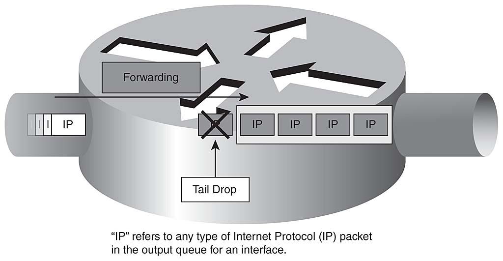
During peak periods, packets cannot be sent immediately because of interface congestion. Instead, the packets are temporarily stored in a queue, waiting to be processed. The amount of time the packet waits in the queue, called the queuing delay, can vary greatly based on network conditions and traffic arrival rates. If the queue is full, newly received packets cannot be buffered anymore and get dropped (tail drop). Figure 1-1 illustrates tail drop. Packets are processed on a first in, first out (FIFO) model in the hardware queue of all router interfaces. Voice conversations are predictable and constant (sampling is every 20 milliseconds by default), but data applications are bursty and greedy. Voice therefore is subject to degradation of quality because of delay, jitter, and packet loss.
Figure 1-1
Each site in a multisite deployment usually is interconnected by an IP WAN, or occasionally by a metropolitan-area network (MAN) such as Metro Ethernet. Bandwidth on WAN links is limited and relatively expensive. The goal is to use the available bandwidth as efficiently as possible. Unnecessary traffic should be removed from the IP WAN links through content filtering, firewalls, and access control lists (ACL). IP WAN acceleration methods for bandwidth optimization should be considered as well. Any period of congestion could result in service degradation unless QoS is deployed throughout the network.
Voice streams are constant and predictable for Cisco audio packets. Typically, the G.729 codec is used across the WAN to best use bandwidth. As a comparison, the G.711 audio codec requires 64 kbps, whereas packetizing the G.711 voice sample in an IP/UDP/RTP header every 20 ms requires 16 kbps plus the Layer 2 header overhead.
Voice is sampled every 20 ms, resulting in 50 packets per second (pps). The IP header is 20 bytes, whereas the UDP header is 8 bytes, and the RTP header is 12 bytes. The 40 bytes of header information must be converted to bits to figure out the packet rate of the overhead. Because a byte has 8 bits, 40 bytes * 8 bits in a byte = 320 bits. The 320 bits are sent 50 times per second based on the 20-ms rate (1 millisecond is 1/1000 of a second, and 20/1000 = .02). So:
.02 * 50 = 1 second
320 bits * 50 = 16,000 bits/sec, or 16 kbps
Voice packets are benign compared to the bandwidth consumed by data applications. Data applications can fill the entire maximum transmission unit (MTU) of an Ethernet frame (1518 bytes or 9216 bytes if jumbo Ethernet frames have been enabled). In comparison to data application packets, voice packets are very small (60 bytes for G.729 and 200 bytes for G.711 with the default 20-ms sampling rate).
In Figure 1-2, a conference bridge has been deployed at the main site. No conference bridge exists at the remote site. If three IP Phones at a remote site join a conference, their RTP streams are sent across the WAN to the conference bridge. The conference bridge, whether using software or hardware resources, mixes the received audio streams and then sends back three unique unicast audio streams to the IP Phones over the IP WAN. The conference bridge removes the receiver's voice from his or her unique RTP stream so that the user does not experience echo because of the delay of traversing the WAN link and mixing RTP audio streams in the conference bridge.
Figure 1-2
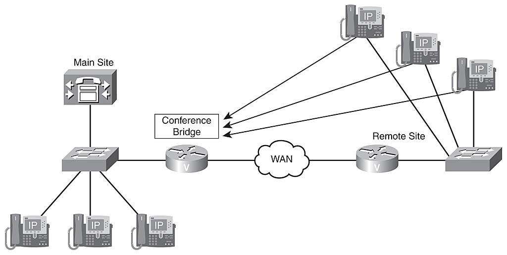
Centralized conference resources cause bandwidth, delay, and capacity challenges in the voice network. Each G.711 RTP stream requires 80 kbps (plus the Layer 2 overhead), resulting in 240 kbps of IP WAN bandwidth consumption by this voice conference. If the conference bridge were not located on the other side of the IP WAN, this traffic would not need to traverse the WAN link, resulting in less delay and bandwidth consumption. If the remote site had a CUCM region configuration that resulted in calls with the G.729 codec back to the main site, the software conferencing resources of CUCM would not be able to mix the audio conversations. Hardware conferencing or hardware transcoder media resources in a voice gateway are required to accommodate G.729 audio conferencing. Local hardware conference resources would remove this need. All centrally located media resources (Music On Hold [MOH], annunciator, conference bridges, videoconferencing, and media termination points) suffer similar bandwidth, delay, and resource exhaustion challenges.
When deploying CUCM in multisite environments, centralized CUCM-based services are accessed over the IP WAN. Affected services include the following:
-
Signaling in CUCM multisite deployments with centralized call processing: Remote Cisco IP Phones register with a centralized CUCM server. Remote MGCP gateways are controlled by a centralized CUCM server that acts as an MGCP call agent.
-
Signaling in CUCM multisite deployments with distributed call processing: In such environments, sites are connected via H.323 (non-gatekeeper-controlled, gatekeeper-controlled, or H.225) or Session Initiation Protocol (SIP) trunks.
-
Media exchange: RTP streams between endpoints located at different sites.
- Other services: These include Cisco IP Phone Extensible Markup Language (XML) services and access to applications such as attendant console, CUCM Assistant, and others.
Figure 1-3 shows a Unified Communications network in which the main site is connected to a remote site through a centralized call-processing environment. The main site is also connected to a remote cluster through an intercluster trunk (ICT) representing a distributed call processing environment. The combination of both centralized and distributed call processing represents a hybrid call-processing model in which small sites use the CUCM resources of the main site, but large remote offices have their own CUCM cluster. On the bottom left of Figure 1-3 is a SIP trunk, typically over a Metro Ethernet connection to an Internet Telephony Service Provider (ITSP). The benefit of the SIP trunk is that the ITSP provides the gateways to the PSTN instead of your providing gateways at the main site.
Figure 1-3
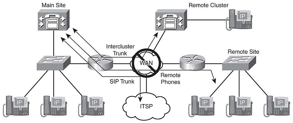
An IP WAN outage in Figure 1-3 will cause an outage of call-processing services for the remote site connected in a centralized fashion. The remote cluster will not suffer a call-processing outage, but the remote cluster will not be able to dial the main site over the IP WAN during the outage. Mission-critical voice applications (voice mail, interactive voice response [IVR], and so on) located at the main site will be unavailable to any of the other sites during the WAN outage.
If the ITSP is using the same links that allow IP WAN connectivity, all calls to and from the public switched telephone network (PSTN) will also be unavailable.
A deployment like the one shown in Figure 1-3 is considered badly designed because of the lack of IP WAN and PSTN backup.
In a multisite deployment, with a single or multiple CUCM clusters, dial plan design requires the consideration of several issues that do not exist in single-site deployments:
-
Overlapping numbers: Users located at different sites can have the same directory numbers assigned. Because directory numbers usually are unique only within a site, a multisite deployment requires a solution for overlapping numbers.
-
Nonconsecutive numbers: Contiguous ranges of numbers are important to summarize call-routing information, analogous to contiguous IP address ranges for route summarization. Such blocks can be represented by one or a few entries in a call-routing table, such as route patterns, dial peer destination patterns, and voice translation rules, which keep the routing table short and simple. If each endpoint requires its own entry in the call-routing table, the table gets too big, lots of memory is required, and lookups take more time. Therefore, nonconsecutive numbers at any site are not optimal for efficient call routing.
-
Variable-length numbering: Some countries, such as the U.S. and Canada, have fixed-length numbering plans for PSTN numbers. Others, such as Mexico and England, have variable-length numbering plans. A problem with variable-length numbers is that the complete length of the number dialed can be determined only by the CUCM route plan by waiting for the interdigit timeout. Waiting for the interdigit timeout, known as the T.302 timer, adds to the post-dial delay, which may annoy users.
-
Direct inward dialing (DID) ranges and E.164 addressing: When considering integration with the PSTN, internally used directory numbers have to be related to external PSTN numbers (E.164 addressing). Depending on the numbering plan (fixed or variable) and services provided by the PSTN, the following solutions are common:
-
Each internal directory number relates to a fixed-length PSTN number: In this case, each internal directory number has its own dedicated PSTN number. The directory number can, but does not have to, match the least-significant digits of the PSTN number. In countries with a fixed numbering plan, such as the North American Numbering Plan (NANP), this usually means that the four-digit office codes are used as internal directory numbers. If these are not unique, digits of office codes or administratively assigned site codes might be added, resulting in five or more digits being used for internal directory numbers.
Another solution is to not reuse any digits of the PSTN number but to simply map each internally used directory number to any PSTN number assigned to the company. In this case, the internal and external numbers do not have anything in common. If the internally used directory number matches the least-significant digits of its corresponding PSTN number, significant digits can be set at the gateway or trunk. Also, general external phone number masks, transformation masks, or prefixes can be configured. This is true because all internal directory numbers are changed to fully qualified PSTN numbers in the same way. Another example is if the internal directory number is composed of parts of the PSTN number and administratively assigned digits such as site codes plus PSTN station codes, or different ranges, such as PSTN station codes 4100 to 4180 that map to directory numbers 1100 to 1180, or totally independent mappings of internal directory numbers to PSTN numbers. In that case, one or more translation rules have to be used for incoming calls, and one or more calling party transformation rules, transformation masks, external phone number masks, or prefixes have to be configured.
-
No DID support in fixed-length numbering plans: To avoid the requirement of one PSTN number per internal directory number when using a fixed-length numbering plan, it is common to disallow DID to an extension. Instead, the PSTN trunk has a single number, and all PSTN calls routed to that number are sent to an attendant, auto-attendant, receptionist, or secretary. From there, the calls are transferred to the appropriate internal extension.
- Internal directory numbers are part of a variable-length number: In countries with variable-length numbering plans, a typically shorter "subscriber" number is assigned to the PSTN trunk, but the PSTN routes all calls starting with this number to the trunk. The caller can add digits to identify the extension. There is no fixed number of additional digits or total digits. However, there is a maximum, usually 32 digits, which provides the freedom to select the length of directory numbers. This maximum length can be less. For example, in E.164 the maximum number is 15 digits, not including the country code. A caller simply adds the appropriate extension to the company's (short) PSTN number when placing a call to a specific user. If only the short PSTN number without an extension is dialed, the call is routed to an attendant within the company. Residential PSTN numbers are usually longer and do not allow additional digits to be added; the feature just described is available only on trunks.
-
-
Type of Number (TON) in ISDN: The calling number (the Automatic Number Identification [ANI]) of calls being received from the PSTN can be represented in different ways:
- As a seven-digit subscriber number
- As a ten-digit number, including the area code
- In international format with the country code in front of the area codeTo standardize the ANI for all calls, the format that is used must be known, and the number has to be transformed accordingly.
- Optimized call routing: Having an IP WAN between sites with PSTN access at all sites allows PSTN toll bypass by sending calls between sites over the IP WAN instead of using the PSTN. In such scenarios, the PSTN should be used as a backup path only in case of WAN failure. Another solution, which extends the idea of toll bypass and can potentially reduce toll charges, is to also use the IP WAN for PSTN calls. With tail-end hop-off (TEHO), the IP WAN is used as much as possible, and the gateway that is closest to the dialed PSTN destination is used for the PSTN breakout.
Overlapping and nonconsecutive numbers
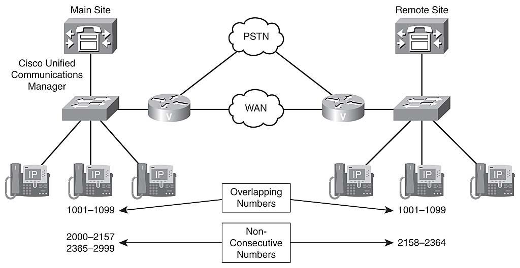
In Figure 1-4, Cisco IP Phones at the main site use directory numbers 1001 to 1099, 2000 to 2157, and 2365 to 2999. At the remote site, 1001 to 1099 and 2158 to 2364 are used. These directory numbers have two issues. First, 1001 to 1099 overlap; these directory numbers exist at both sites, so they are not unique throughout the complete deployment. This causes a problem: If a user in the remote site dialed only the four digits 1001, which phone would ring? This issue of overlapping dial plans needs to be addressed by digit manipulation. In addition, the nonconsecutive use of the range 2000 to 2999 (with some duplicate numbers at the two sites) would require a significant number of additional entries in call-routing tables because the ranges can hardly be summarized by one (or a few) entries.
Figure 1-4
Fixed versus variable-length numbering plans
A fixed numbering plan features fixed-length area codes and local numbers. An open numbering plan features variance in length of area code or local number, or both, within the country.
Table 1-1 contrasts the NANP and a variable-length numbering plan -- Germany's numbering plan in this example.
Table 1-1
| Component | Description | Fixed Numbering Plan (NANP) | Variable-Length Numbering Plan (Germany) |
|---|---|---|---|
| Country code | A code of one to three digits is used to reach the particular telephone system for each nation or special service. Obtain the E.164 standard from http://itu.org to see all international country codes. | 1 | 49 |
| Area code | Used within many nations to route calls to a particular city, region, or special service. Depending on the nation or region, it may also be called a numbering plan area, subscriber trunk dialing code, national destination code, or routing code. | Three digits | Three to five digits |
| Subscriber number | Represents the specific telephone number to be dialed, but it does not include the country code, area code (if applicable), international prefix, or trunk prefix. | Three-digit exchange code plus a four-digit station code | Three or more digits |
| Trunk prefix | The initial digits to be dialed in a domestic call, before the area code and the subscriber number. | 1 | 0 |
| Access code | A number that is traditionally dialed first "to get out to the PSTN," used in PBXs and VoIP systems. | 9 | 0 |
| International prefix | The code dialed before an international number (country code, area code if any, and then subscriber number). | 011 | 00 or + (+ is used by cell phones) |
Examples:
- Within the U.S.: 9-1-408-555-1234 or 1-555-1234 (within the same area code)
- U.S. to Germany: 9-011-49-404-132670
- Within Germany: 0-0-404-132670 or 0-132670 (within the same area code)
- Germany to the U.S.: 0-00-1-408-555-1234 (Note: the 1 in 00-1-408 is the U.S. country code, not the trunk prefix.)
The NANP PSTN number is 408-555-1234, DID is not used, and all calls placed to the main site are handled by an attendant. There is a remote site in Germany with the E.164 PSTN number +49 404 13267. Four-digit extensions are used at the German location, and DID is allowed because digits can be added to the PSTN number. When calling the German office attendant (not knowing a specific extension), U.S. users would dial 9-011-49-404-13267. Note how the + is replaced by the international prefix 011 and the access code 9. If the phone with extension 1001 should be called directly, 9-011-49-404-13267-1001 has to be dialed.
Variable-length numbering, E.164 addressing and DID
Figure 1-5 illustrates an example in which the main site with CUCM resides in the U.S. and a remote site without CUCM resides in Germany. The NANP PSTN number in the U.S. is 408-555-1234. Note that DID is not used, because all calls placed to the main site are handled by an attendant. A remote site in Germany has PSTN number +49 404 13267. Four-digit extensions are used at the German location, and DID is allowed because digits can be added to the PSTN number. When calling the German office attendant (not knowing a specific extension), U.S. users would dial 9-011-49-404-13267. If the phone with extension 1001 should be called directly, 9-011-49-404-13267-1001 has to be dialed.
Figure 1-5
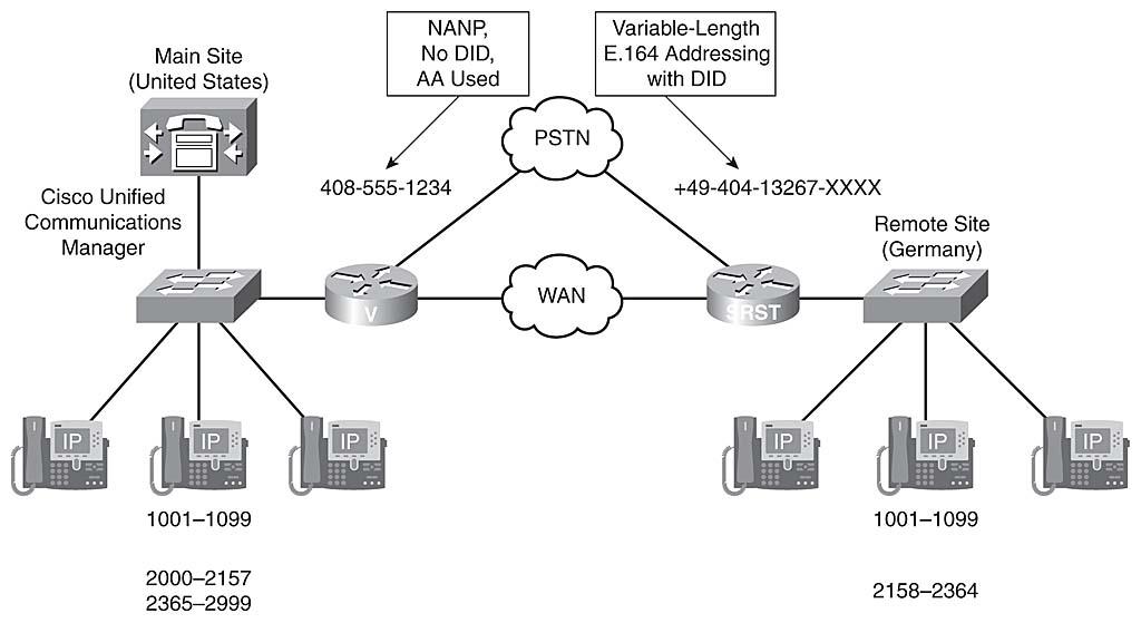
The logic of routing calls by CUCM over the WAN or through the PSTN is appropriately transparent to the phone user.
Optimized call routing and PSTN backup
There are two ways to save costs for PSTN calls in a multisite deployment:
-
Total bypass: Calls between sites within an organization that use the IP WAN instead of the PSTN. The PSTN is used for intersite calls only if calls over the IP WAN are not possible—either because of a WAN failure or because the call is not admitted by Call Admission Control (CAC).
- Tail-end hop-off (TEHO): Extends the concept of toll bypass by also using the IP WAN for calls to the remote destinations in the PSTN. With TEHO, the IP WAN is used as much as possible, and PSTN breakout occurs at the gateway that is located closest to the dialed PSTN destination. Local PSTN breakout is used as a backup in case of IP WAN or CAC.
In the example shown in Figure 1-6, a call from Chicago to San Jose would be routed as follows:
- The Chicago CUCM Express user dials 9-1-408-555-6666, a PSTN phone located in San Jose.
- The call is routed from Chicago CUCM Express Router to the San Jose CUCM cluster over the IP WAN with either SIP or H.323.
- The San Jose CUCM routes the call to the San Jose gateway, which breaks out to the PSTN with what now becomes a local inexpensive call to the San Jose PSTN.
- The San Jose PSTN Central Office routes the call, and the phone rings.
Figure 1-6
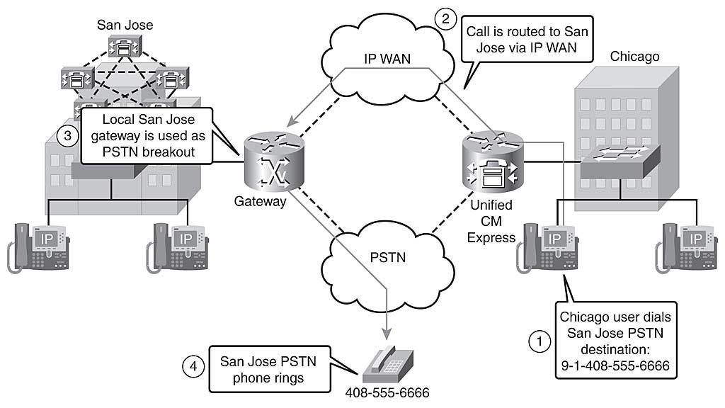
If the WAN were unavailable for any reason before the call, the Chicago Gateway would have to be properly configured to route the call with the appropriate digit manipulation through the PSTN at a potentially higher toll cost to the San Jose PSTN phone.
In single-site deployments, CUCM servers and IP Phones usually use private IP addresses because there is no need to communicate with the outside IP world. NAT is not configured for the phone subnets, and attacks from the outside are impossible. In multisite deployments, however, IP Security (IPsec) virtual private network (VPN) tunnels can be used between sites. The VPN tunnels allow only intersite communication; access to the protected internal networks is not possible from the outside—only from the other site through the tunnel. Therefore, attacks from the outside are blocked at the gateway. To configure IPsec VPNs, the VPN tunnel must be configured to terminate on the two gateways in the different sites. Sometimes this is not possible; for instance, the two sites may be under different administration, or perhaps security policies do not allow the configuration of IPsec VPNs.
In such a case, or when connecting to a public service such as an ITSP, NAT has to be configured for CUCM servers and IP Phones. Cisco calls this Hosted NAT Traversal for Session Border Controllers.
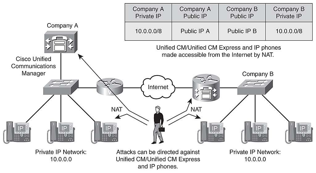
In Figure 1-7, Company A and Company B both use IP network 10.0.0.0/8 internally. To communicate over the Internet, the private addresses are translated into public IP addresses. Company A uses public IP network A, and Company B uses public IP network B. All CUCM servers and IP Phones can be reached from the Internet and communicate with each other.
As soon as CUCM servers and IP Phones can be reached with public IP addresses, they are subject to attacks from the outside world, introducing potential security issues.
Figure 1-7
Download and read "Identifying Issues in a Multisite Deployment" in its entirety.


