What is Fibre Channel? History, layers, components and design
Fibre Channel is a high-speed networking technology primarily used for transmitting data among data centers, computer servers, switches and storage at data rates of up to 128 gigabits per second (Gbps). The technology connects computers, mainframes and supercomputers to storage area networks (SANs) while enabling the delivery of block data in an in-order, lossless, low-latency fashion.
The standard was developed to overcome the limitations of the Small Computer System Interface (SCSI) and High-Performance Parallel Interface (HIPPI) by filling the need for a reliable and scalable high-throughput and low-latency protocol and interface, particularly for mission-critical workloads and applications that require real-time data updates.
When it was originally developed, the technology was called Fiber Channel (U.S. spelling). At the time, it was meant to run over optical fiber cables. However, the U.K. spelling was universally adopted when support for copper cabling was added. As a result, the protocol is now usually spelled as Fibre Channel.
What is Fibre Channel used for?
Fibre Channel is especially suited for connecting servers to shared storage devices and interconnecting storage controllers and drives. The technology is also preferred in data centers that process mission-critical workloads and/or require synchronous data mirroring for real-time data replication, continuous availability and reliable disaster recovery.
The flexibility of Fibre Channel and its ability to provide in-order, lossless, high-speed delivery of block data make it suitable for applications that require low-latency data transfer and/or use block storage. These include high-speed online transaction processing (OLTP) databases, such as those used for the following:
- Online banking.
- ATM transactions.
- E-commerce order processing.
- E-commerce payments management.
- E-commerce inventory management.
- Hotel and flight bookings.
- Retail in-store POS systems.
In general, OLTP databases and Fibre Channel can benefit any application that requires frequent, rapid or real-time data updates.
Fibre Channel is also used in large virtualized environments where a large number of virtual machines (VMs) need fast shared storage. Data centers that need to set up fault-tolerant access paths with automatic failover also typically use Fibre Channel.
Why Fibre Channel?
Fibre Channel offers point-to-point, switched and loop interfaces to deliver lossless, in-order, raw block data. Because Fibre Channel is many times faster than SCSI, it has replaced that technology as the transmission interface between servers and clustered storage devices. However, Fibre Channel networks still can transport SCSI commands and information units using the Fibre Channel Protocol (FCP). It is designed to interoperate with not just SCSI but also Internet Protocol (IP) and other protocols.
Fibre Channel is also an option, along with remote direct memory access over Ethernet and InfiniBand, for high-performance computing environments transporting data under the non-volatile memory express over Fabrics (NVMe-oF) specification to improve flash storage performance over a network.
Benefits and limitations of Fibre Channel
Fibre Channel defines the physical network infrastructure as well as data transport protocols, making it a complete networking offering. It ensures fast, low-latency data delivery. The technology also supports multiple speeds, with products available for different applications and use cases.
The technology supports asynchronous and synchronous data mirroring for disaster recovery. Asynchronous mirroring is suitable when the data center setup includes a secondary server that can take over when a primary server goes offline. This method introduces some lag in data synchronization. If the lag is not acceptable, synchronous data mirroring can be implemented with Fibre Channel to provide high availability, reliable disaster recovery and near-zero data loss.
Fibre Channel supports multiple upper-layer protocols, including SCSI, TCP/IP and NVMe. Regardless of which protocol is used, the technology remains transparent and autonomous. Furthermore, it ensures that communication remains protected with support for access controls, encryption and authentication.
Lastly, Fibre Channel includes features for load balancing and self-healing. It is also scalable, provides flow control (end-to-end and device-to-device), and supports multi-pathing and routing -- without frame-dropping or data loss.
One of the main drawbacks of Fibre Channel SANs is that they are more expensive than Ethernet using iSCSI. That said, organizations can control the cost by choosing the right configuration for their needs and avoiding implementing unnecessary cables, switches and other components.
Another drawback is that -- unlike other more prevalent technologies, such as Ethernet and iSCSI -- Fibre Channel setup and operation require specific expertise and skilled personnel. These resources might be out of bounds for smaller, budget-constrained organizations.
Fibre Channel history and standards
The Fibre Channel Physical and Signaling Interface (FC-PH) standard was created for SANs. Development of the standard started in 1988 as part of the Intelligent Peripheral Interface (IPI) Enhanced Physical Project. The first draft of the standard was completed in 1989. The American National Standards Institute (ANSI) approved the FC-PH standard in 1994. Since then, two more related standards have emerged:
- Fibre Channel Physical Interface (FC-PI). This describes the point-to-point physical interface of a high-performance serial link to support higher-level protocols.
- Fibre Channel Framing and Signaling (FC-FS). This describes the framing and signaling requirements for Fibre Channel links.
Fibre Channel was the first serial storage transport to hit gigabit speeds; its performance has consistently doubled every few years for the last 20 years.
Today, the INCITS/Fibre Channel Technical Committee develops standards for Fibre Channel. INCITS (InterNational Committee for Information Technology Standards) is an open, collaborative community that creates IT standards for globally transformative technologies, including Fibre Channel.
Until January 2022, INCITS/Fibre Channel was known as INCITS/T11. Many industry organizations and member companies use the newer INCITS/T11 nomenclature when referring to Fibre Channel technologies. Most also support the development of such standards since they promote interoperability among the components manufactured by different companies and protect users by ensuring reliability and high performance. Supporters of these standards include the Fibre Channel Industry Association (FCIA).
A Task Group within the INCITS/Fibre Channel Technical Committee is responsible for defining Fibre Channel encoding and protocols. This Task Group, named INCITS/Fibre Channel Interconnection Schemes (formerly known as INCITS/T11.3 until January 2022), defines the encoding and low-level protocols that allow Fibre Channel to carry numerous upper-level storage and networking protocols, including the following:
- FCP (SCSI).
- NVMe over FC.
- FC-SB-6 (FICON).
Another Task Group within the Technical Committee, named INCITS/Fibre Channel Physical Variants, is responsible for all projects dealing with the Physical Variants of Fibre Channel. These include requirements related to the following components:
- Media.
- Connectors.
- Transmitters.
- Receivers.
Apart from the INCITS/Fibre Channel Technical Committee, several other standards organizations are also involved in developing Fibre Channel standards and protocols. One of them, the International Organization for Standardization (ISO), has developed the ISO/IEC 14165-141:2001 standard that describes the general requirements -- such as the physical and signaling interfaces, switch fabric requirements and generic services -- for topology-independent fabrics supporting the FC-PH for the communications transport medium that provides switched interconnect between pairs of user attachment points.
The ISO describes Fibre Channel as a data transport vehicle for Upper Level Protocols (ULPs), such as SCSI command sets, IP and ANSI/IEEE 802.2.
ANSI has also developed a standard for Fibre Channel: ANSI INCITS 230-1994 (R1999). This standard -- formerly known as X3.230-1994 (R1999) -- describes the FC-PH of a high-performance serial Fibre Channel link to support ULPs associated with HIPPI, IPI, SCSI, IP and others. An amendment to the standard -- ANSI INCITS 230-1994/AM 2-1999, formerly ANSI X3.230-1994/AM 2-1999 -- clarifies the bit error definition in the original standard and corrects some other errors and inconsistencies.
In addition to nonprofits such as INCITS, ISO and ANSI, for-profit companies are also involved in the development of Fibre Channel standards. For example, Broadcom's Brocade Storage Networking division has helped create and edit standards, including Fibre Channel for SCSI (FCP-6), NVMe over FC (FC-NVMe-x) and Switch Fabric (FC-SW-x).
Fibre Channel and NVMe-oF specification
NVM Express is a 100-plus-member nonprofit organization that developed the NVMe protocol to connect solid-state drives (SSDs) to Peripheral Component Interconnect Express (PCIe) buses while providing lossless high-speed data transfers. The organization then developed NVMe-oF.
Prior to the release of NVMe-oF, only three connection types were available for SANs: iSCSI, serial attached SCSI and FCP. These technologies were suitable for hard drives and tape storage systems; however, performance-wise, they fell short for SSDs and flash memory.
NVM Express Inc. published version 1.0 (NVMe-oF 1.0) of the NVMe-oF specification on June 5, 2016. This new specification extended NVMe technology and network protocol to additional transports beyond PCIe, including Ethernet and Fibre Channel, to enable faster connectivity between storage and servers.
In 2019, NVMe-oF 1.1 was released to add finer control over I/O resource management and end-to-end flow control, to add support for NVMe/TCP and to improve fabric communication. Another version, revision 1.1a, was published in 2021.
The T11 committee of INCITS developed a frame format and mapping protocol for applying NVMe-oF to Fibre Channel. It finalized and submitted the first version of the mapping protocol, under the FC-NVMe standard banner, to INCITS in August 2017 and released FC-NVMe 2 in 2020.
NVMe 2.0 includes several changes over the previous protocol, including support for TLS 1.2. It also offers enhanced error recovery by detecting errors before they can even reach the protocol layer.
The NVMe-oF protocol offers faster connectivity between storage and server applications, efficient CPU usage, lower latency and improved flash storage management. It also increases the efficiency of storage I/O processing and reduces performance bottlenecks for modern applications. Finally, by facilitating a shared storage infrastructure, it allows for the consolidation of SAN and direct-attached storage (DAS) application infrastructure silos.
How Fibre Channel works
The Fibre Channel protocol includes three main elements: frames, sequences and exchanges. A frame is a packet of data of up to 2,112 bytes that will be transferred from Point A to Point B. Each frame consists of an FC header, payload and Cyclic Redundancy Check error-detecting code. A frame, or a set of frames, is involved in larger data transfers -- up to multi-megabytes -- to create a sequence.
Exchanges refer to the interactions between two Fibre Channel ports. An exchange includes a set of commands and responses. Within the same exchange, individual frames are always delivered in order. The FC-NVMe protocol uses an exchange as a single "command/response."
Fibre Channel technology enables individual exchanges to take different routes through the fabric. As a result, the fabric can efficiently use multiple paths between individual switches to improve performance and reduce latency.
Fibre Channel devices can be as far as 10 kilometers apart -- approximately six miles -- if multimodal optical fiber is used as the physical cable medium. Optical fiber is not required for shorter distances. Fibre Channel also works using coaxial cable and ordinary telephone twisted pair. When using copper cabling, however, it is recommended that distances not exceed 100 feet.
Fibre channel networking speeds
Historically, Fibre Channel networking speeds have been labeled in Gbps -- 1 Gbps, 2 Gbps, 4 Gbps, 8 Gbps, 16 Gbps, 32 Gbps, 64 Gbps and 128 Gbps -- representing throughput performance. The naming convention was changed to Gigabit Fibre Channel (GFC) -- 1GFC, 2GFC, 4GFC, 8GFC, etc. -- by the FCIA.
Here, 1GFC refers to a throughput of 100 MB/s, whereas 1 Gbit Ethernet refers to throughput of 120 MB/s. Also, the baud rate -- the rate at which information is transferred in a communication channel -- for 1GFC is 1.0625 Gigabaud.
The throughput and baud rates provided by the various Fibre Channel products are tabulated below.
| FC product | Payload throughput | Baud rate |
| 1 Gb | 100 MB/s | 1.0625 |
| 2 GB | 200 MB/s | 2.125 |
| 4 Gb | 400 MB/s | 4.25 |
| 8 Gb | 800 MB/s | 8.5 |
| 16 Gb | 1600 MB/s | 14.025 |
| 32 Gb | 3200 MB/s | 28.05 |
| 128 Gb | 12800 MB/s | 112.2 |
Encoding is an important consideration in Fibre Channel. Fibre Channel does not increase the speed to compensate for the overhead involved in 8b/10b encoding, although it does slightly increase the speed to compensate for the headers. Encoding with 64b/66b (10GFC and 16GFC) is much more efficient since the overhead is lower compared to 8b/10b encoding.
Each Fibre Channel is backward compatible to at least two previous generations. For example, 8GFC maintains backward compatibility with 4GFC and 2GFC.
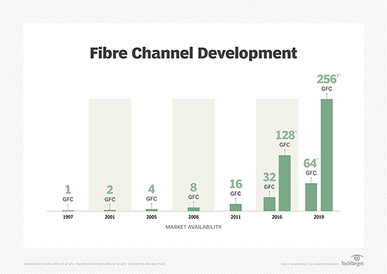
With Generation 5 Fibre Channel, called 16GFC, the encoding mechanism changed. Gen 5 performs at a line rate of 15.025 Gbaud with single-lane throughput of 1,600 megabytes per second (MBps) and bidirectional throughput of 3,200 MBps, according to FCIA's roadmap.
Gen 6 Fibre Channel added features such as N_Port ID virtualization, better energy efficiency and forward error correction to improve the reliability of Fibre Channel links and prevent application performance degradation and outages by avoiding data stream errors. It comes in 32GFC and 128GFC. The former is single lane at a line rate of 28.05 Gbaud with 6,400 MBps throughput; the latter, with parallel functionality, has four lanes (28.5 Gbaud x 4) for 112.2 Gbaud line rate performance and 25,660 MBps throughput.
The FCIA roadmap extends well into the future to 1 Terabit Fibre Channel (1TFC), which is slated to perform at 204,800 MBps and have its T11 specification completed in 2029. Between that and Gen 6 Fibre Channel are generations that include single-lane 64GFC (57.8 Gbaud, 12,800 MBps) and four-lane 256GFC (4 x 57.8 Gbaud, 51,200 MBps). The roadmap also lists more advanced 128GFC and 256GFC versions with estimated T11 specification completion dates of 2023 and 2026, respectively, and a 512GFC (2026 for T11, 102,400 MBps) edition.
Fibre Channel layers
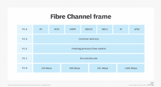
Fibre Channel defines layers of communication similar to -- but different from -- the Open Systems Interconnection (OSI) model. Like OSI, Fibre Channel splits the process of network communication into layers, or groups, of related functions. OSI includes seven such layers, while Fibre Channel has five layers. IP networks use packets, and Fibre Channel relies on frames to foster communication between nodes.
These are the five layers of a Fibre Channel frame:
- Upper Layer Protocol Mapping: FC Layer 4.
- Common Services Layer: FC Layer 3.
- Signaling/Framing Layer: FC Layer 2.
- Transmission Layer: FC Layer 1.
- Physical Layer: FC Layer 0.
Within a Fibre Channel topology, each of the five frame layers works with the ones below and above it to deliver distinct functions. Innovation is a central advantage of a layered design; a new technology can be introduced into a layer without disrupting or requiring the redesign of the other layers.
For example, cabling, such as copper or optical cables, fits into the physical layer (FC-0). If a new cable design or technology is introduced, it would only need to fit the compatibility requirements of Layer 0.
Fibre Channel components
There are four main Fibre Channel components: switches, host bus adapters (HBAs), ports and software.
Switches. A Fibre Channel switch enables a high-availability, low-latency, high-performance and lossless data transfer in a Fibre Channel fabric. It determines the origin and destination of data packets to send to their intended destination. As the main components used in a SAN, Fibre Channel switches can interconnect thousands of storage ports and servers. Features in Fibre Channel director-class switches include zoning to block unwanted traffic and encryption.
Host bus adapters. Fibre Channel HBAs are cards, such as circuit boards or IC adapters, that connect servers to storage and network devices. An HBA is similar in principle to an Ethernet network adapter. It offloads server processing of data storage tasks and improves server performance. When Fibre Channel and Ethernet networks first converged, HBA vendors developed converged network adapters (CNAs) that combine the functionality of a Fibre Channel HBA with an Ethernet network interface card (NIC).
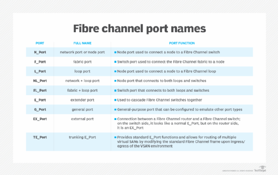
Ports. Fibre Channel switches and HBAs connect to each other and to servers through physical or virtual ports. Data in a Fibre Channel fabric node is sent and received through ports that come in an assortment of logical configurations. Fibre Channel switches can range from having fewer than 10 ports to hundreds of ports in a chassis. The connections between ports and HBAs are established using physical copper or optical cables. The three main FC port types are the N-port, F-port and E-port, although port names also exist.
Software. Fibre Channel installations depend on a software layer for device drivers, along with control and management between hosts, ports and devices. Software offers a visualization of the Fibre Channel environment and enables oversight and control of Fibre Channel resources from a central console.
Fibre Channel design and configuration
The FCP supports three main topologies to link Fibre Channel ports together and enable devices, such as switches and HBAs, to connect servers to a network and storage.
Point-to-point. The simplest and most limited Fibre Channel topology connects two devices or ports, such as linking a host server to a DAS.
Arbitrated loop. Devices are linked in a circular, ringlike manner. Each node or device on the ring sends data to the next node. Bandwidth is shared among all devices. If one device or port fails, all of them could be interrupted unless a Fibre Channel hub is used to connect multiple devices and bypass failed ports. The maximum number of devices that can be in an arbitrated loop is 127; for practical reasons, the number is limited to far fewer.
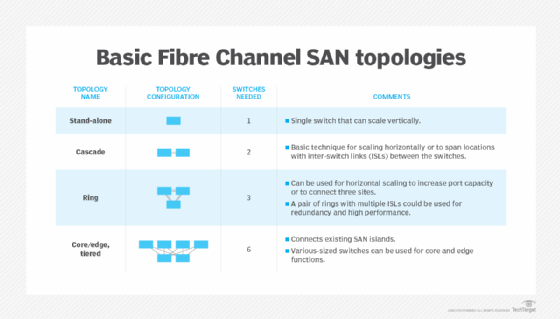
Switched fabric. All devices in this topology connect and communicate using switches, which optimize data paths using the Fabric Shortest Path First routing protocol and let multiple pairs of ports interconnect concurrently. Ports do not connect directly but, instead, flow through switches. When one port fails, the operation of other ports should not be affected. All nodes in the fabric work simultaneously, increasing efficiency, while redundancy of paths between devices increases availability. Switches can be added to the fabric without taking the network down.
Interconnection types within the switched fabric topology include the following:
- Single-switch topology. This is the simplest switch topology. There is just one switch and no interswitch links. This topology is seldom used because it presents a single point of failure.
- Cascade topology. This topology lines up switches and connects them together, one after the other, in the manner of a queue. Adding an interswitch link to interconnect the first and last switch in the cascade closes the loop to form a switched fabric ring topology.
- Mesh topology. This occurs when every switch in the Fibre Channel fabric connects to every other switch.
- Core-edge topology. This takes a tiered approach to a mesh topology by using higher-performance director switches as core switches. It connects servers to the edge fabric and storage to core switches. These, in turn, are interconnected to facilitate communication between servers and storage.
- Edge-core-edge topology. This enables storage and servers to connect to the edge fabric, but core switch communication is used only to connect and scale edge switches. This topology configuration helps extend the flow of SAN traffic across long distances and eases the management of storage and servers when each are at different edges of a Fibre Channel fabric.
Fibre Channel vs. iSCSi SANs
As a Layer 2 switching technology, hardware handles the entire protocol in Fibre Channel fabrics. By contrast, iSCSI is a Layer 3 switching technology that runs over Ethernet. Here, software, hardware or both software and hardware can control the protocol.
Ethernet-based iSCSI transports SCSI packets over a TCP/IP network. Because iSCSI uses commonplace Ethernet, it doesn't require buying costly and often complex adapters and network cards. This makes iSCSI cheaper and easier to deploy.
Even so, most data centers with a high-capacity FC SAN for mission-critical workloads prefer Fibre Channel networking over iSCSI. That's mostly because Fibre Channel is a proven technology that can reliably handle demanding workloads without dropping data packets.
That said, specialized installation and configuration skills are required to properly get an FC SAN up and running. IT staff can implement an iSCSI SAN on an existing network using common switches and Ethernet NICs. With iSCSI, there is only one network to build and manage, while Fibre Channel requires two networks: an FC SAN for storage and an Ethernet network for everything else.
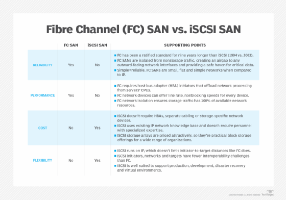
All major storage vendors offer iSCSI SAN arrays in addition to their Fibre Channel mainstays. Some sell unified, multiprotocol storage platforms with both iSCSI and Fibre Channel.
Fibre Channel vs. Ethernet
Fibre Channel and Ethernet are two different types of network technologies that traditionally serve different purposes across the enterprise. As a result, they are often used together in a complementary manner.
Fibre Channel
In general terms, Fibre Channel supports the in-order and lossless transmission of raw block data. These capabilities have made it indispensable for high-performance data handling between servers and storage subsystems.
Fibre Channel networks operate at powers-of-two-based speeds, ranging from 1 Gbps to 128 Gbps, with 256 Gbps and 512 Gbps versions coming in the future.
Fibre Channel includes security features like port binding, zoning and LUN masking. Also, most deployments are isolated within the enterprise and are not connected to other networks or the internet. This provides natural security from intrusion and hacking.
Ethernet
By comparison, Ethernet provides general-purpose, out-of-order, loss-tolerant packet networking technology used in local area networks (LANs) and wide area networks. Ethernet is broadly available and highly standardized. The standards it's based on include IEEE 802.3 and the conventional OSI layer model. Ethernet also supports long cable distances and handles speeds ranging from 1 Gbps to 400 Gbps.
Its wide adoption and vulnerable TCP/IP protocol make Ethernet networks and connected systems more vulnerable to attack, requiring additional security measures. Still, Ethernet is often the network of choice for basic storage connectivity, such as network-attached storage.
Ethernet's prevalence can also be an advantage in terms of the availability of skilled personnel. In contrast, FC SAN requires highly specialized skills.
What is Fibre Channel over Ethernet?
Given the tradeoffs between Fibre Channel and Ethernet, designers have sought ways to connect the two different technologies. Fibre Channel over Ethernet (FCoE) is a network approach that encapsulates Fibre Channel data and data formats over common 10 Gbps and faster Ethernet networks. This essentially replaces Layer 0 and Layer 1 of the Fibre Channel stack with corresponding Ethernet layers and enables Fibre Channel commands and data to travel over Ethernet LANs.
However, FCoE is not a routable protocol and will not work over routed IP networks. FCoE is an international standard covered in the T11 FC-BB-5 standard published in 2009. When implemented properly, FCoE integrates Fibre Channel with Ethernet-based applications and management software.
FCoE adds three major capabilities to enable Fibre Channel operation over Ethernet:
- Fibre Channel frames must be encapsulated into Ethernet frames.
- FCoE must facilitate a lossless environment where frames are not lost and retransmitted in response to network congestion.
- FCoE must map Fibre Channel N_port IDs to conventional Ethernet MAC addresses. Computers can access FCoE using CNAs, which provide both Fibre Channel HBA and Ethernet NIC functions on the same device.
Fibre Channel vs. fiber optic
Fibre Channel supports both copper and optical fiber cabling depending on the deployment. Fibre Channel copper cabling is well-suited for short-distance connections, up to about 100 feet. Optical connections using fiber optic cables are intended for medium- to long-distance connections, up to about six miles, such as campus networks and metropolitan area networks.
The choice of cable is governed by the HBA port choice and the ports available on Fiber Channel switches and storage gear. In many cases, hardware will provide port options for both copper and fiber cabling that users can deploy as required.
Compare Fibre Channel and iSCSI in terms of SAN performance, ease of use, manageability, overall package and total cost of ownership.
Continue Reading About What is Fibre Channel? History, layers, components and design
Dig Deeper on Storage architecture and strategy
-
![]()
What is a SAN switch? How it works and compares to other network switches
-
![]()
What is a Fibre Channel switch (FC switch)? How it works, benefits and comparison to Ethernet switch
-
![]()
What is Fibre Channel over Ethernet (FCoE)? How it works, benefits, challenges and use cases
-
![]()
What is NVMe over Fibre Channel (NVMe over FC)? Definition and Guide


