VLAN (virtual LAN)
What is a VLAN (virtual LAN)?
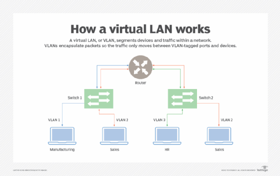
A virtual LAN (VLAN) is a logical overlay network that groups together a subset of devices that share a physical LAN, isolating the traffic for each group.
A LAN is a group of computers or other devices in the same place -- e.g., the same building or campus -- that share the same physical network. A LAN is usually associated with an Ethernet (Layer 2) broadcast domain, which is the set of network devices an Ethernet broadcast packet can reach.
Computers on the LAN connect to the same network switch, either directly or through wireless access points (APs) connected to the same switch. Computers can also connect to one of a set of interconnected switches, such as a set of access switches that all connect up to a backbone switch. Once traffic crosses a router and engages Layer 3 (IP-related) functions, it is not considered to be on the same LAN, even if everything stays in the same building or floor. As a result, a location could have many interconnected LANs.
A VLAN, like the LAN it sits atop, operates at Layer 2 of the network, the Ethernet level. VLANs partition a single switched network into a set of overlaid virtual networks that can meet different functional and security requirements. This partitioning avoids the need to have multiple, distinct physical networks for different use cases.
The purpose of a VLAN
Network engineers use VLANs for multiple reasons, including the following:
- to improve performance
- to tighten security
- to ease administration
Improve performance
VLANs can improve performance for devices on them by reducing the amount of traffic a given endpoint sees and processes. VLANs break up broadcast domains, reducing the number of other hosts from which any given device sees broadcasts. For example, if all desktop voice over IP phones are on one VLAN and all workstations are on another, phones won't see any workstation-generated broadcast traffic and vice versa. Each can devote its network resources to relevant traffic only.
Engineers can also define different traffic-handling rules per VLAN. For example, they can set rules to prioritize video traffic on a VLAN that connects conference room equipment to help guarantee the performance of telepresence devices.
Tighten security
VLAN partitioning can also improve security by enabling a higher degree of control over which devices have access to each other. For example, network teams may restrict management access to network gear or IoT devices to specific VLANs.
Ease administration
Using VLANs to group endpoints also enables administrators to group devices for purely administrative, nontechnical purposes. For example, they may put all accounting computers on one VLAN, all human resources computers on another and so on.
Types of VLANs
VLANs can be port-based (sometimes called static) or use-based (sometimes called dynamic).
Port-based or static VLAN
Network engineers create port-based VLANs by assigning ports on a network switch to a VLAN. Those ports only communicate on the assigned VLANs, and each port is on one VLAN only. While port-based VLANs are sometimes called static VLANs, it's important to remember they aren't truly static because the VLANs assigned to the port can be changed on the fly, manually or by network automation.
Use-based or dynamic VLAN
Network engineers create use-based VLANs by assigning traffic to a VLAN dynamically, based on the traffic type or the device creating the traffic. A port might be assigned to a VLAN based on the identity of the device attached -- as indicated by a security certificate -- or on the network protocols in use. One port can be associated with multiple dynamic VLANs. Changing which device is connected through a port, or even how the existing device is used, might change the VLAN assigned to the port.
VLAN use cases
Some VLANs have simple and practical goals, such as segregating printer access. Administrators can set them up to enable computers on any given VLAN to see the printers also on that VLAN but not those outside it.
Other VLANs serve more complex purposes. For example, computers in a retail banking department cannot interact directly with computers in the trading departments. Setting up separate VLANs for the departments is one way network engineers can enforce such segregation.
How VLANs work
A VLAN is identified on network switches by a VLAN ID. Each port on a switch can have one or more VLAN IDs assigned to it and will land in a default VLAN if no other one is assigned. Each VLAN provides data-link access to all hosts connected to switch ports configured with its VLAN ID.
A VLAN ID is translated to a VLAN tag, a 12-bit field in the header data of every Ethernet frame sent to that VLAN. Because a tag is 12 bits long, up to 4,096 VLANs can be defined per switching domain. VLAN tagging is defined by IEEE in the 802.1Q standard.
When an Ethernet frame is received from an attached host, it has no VLAN tag. The switch adds the VLAN tag. In a static VLAN, the switch inserts the tag associated with the ingress port's VLAN ID. In a dynamic VLAN, it inserts the tag associated with that device's ID or the type of traffic it generates.
Switches forward tagged frames toward their destination media access control address, forwarding only to ports with which the VLAN is associated. Broadcast, unknown unicast and multicast traffic is forwarded to all ports in the VLAN. Trunk links between switches know which VLANs span the switches, accepting and passing along all traffic for any VLAN in use on both sides of the trunk. When a frame reaches its destination switch port, the VLAN tag is removed before the frame is transmitted to the destination device.
Spanning Tree Protocol (STP) is used to create loop-free topology among the switches in each Layer 2 domain. A per-VLAN STP instance can be used, which enables different Layer 2 topologies. A multi-instance STP can also be used to reduce STP overhead if the topology is the same among multiple VLANs.
Disadvantages of VLANs
VLANs help control broadcast traffic, tighten security, ease administration and improve performance. But they have some disadvantages, too.
Limit of 4,096 VLANs per switching domain
One disadvantage of VLANs in a modern data center or cloud infrastructure is the limit of 4,096 VLANs per switching domain. A single network segment may host tens of thousands of systems and hundreds or thousands of distinct tenant organizations, each of which may need tens or hundreds of VLANs.
To address this limitation, other protocols have been created, including Virtual Extensible LAN, Network Virtualization using Generic Routing Encapsulation and Generic Network Virtualization Encapsulation. They support larger tags, which enables more VLANs to be defined, and the ability to tunnel Layer 2 frames within Layer 3 packets.
Managing spanning tree structures
Another disadvantage is that, when VLANs are numerous and large, the network can have a difficult time managing the spanning tree structures needed to prevent traffic loops. The easiest fix for this is to remove redundant links from the network. Unfortunately, that then leaves the network vulnerable to a single point of failure anywhere a redundant link was removed.
VLAN identification with wall jacks and APs
Another challenge with VLANs is it can be difficult to ensure easy identification of the VLANs to which a given wall jack or AP has access. This can make it more difficult for end users and field service support staff when they attempt to connect something new to the network.
Another disadvantage that isn't unique to VLANs but still affects them is poor planning, which makes the overall VLAN plan overly complicated, brittle and difficult to maintain as needs and underlying network equipment change.