frequency-division multiplexing (FDM)
What is frequency-division multiplexing (FDM)?
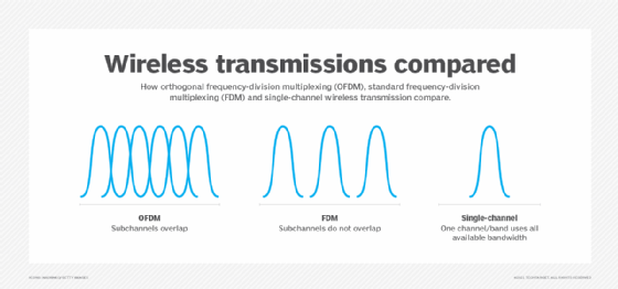
In frequency-division multiplexing (FDM), multiple signals are combined for transmission on a single communications line or channel, with each signal assigned to a different frequency (subchannel) within the main channel.
To accommodate the successful transmission of multiple signals over a single line, FDM separates assigned bands by strips of unused frequencies called guard bands. This prevents overlapping between signal frequencies over a shared medium.
A signal is generated and modulated by a sending device and is carried over the separated bands. The modulated signals are combined using a multiplexer (mux) and transmitted over the communication channel. At the receiving end, the combined signal goes through a demultiplexer (demux) to extract the individual signals.
What are multiplexers and demultiplexers in frequency-division multiplexing?
In FDM, a two-way communications circuit requires a mux/demux at either end. Multiplexing is used when frequencies (signals) of lower bandwidth are transmitted through a channel with a higher bandwidth.
Consider a long-distance cable with a bandwidth of 3 megahertz. In theory, it should be possible to place and transmit 1,000 signals, each 3 kilohertz (kHz) wide, in the channel. The circuit that does this is the multiplexer. It accepts inputs from each individual user and generates a signal on a different frequency for each input. This results in a single, high-bandwidth, complex signal containing data from all users.
At the other end, the demultiplexer separates individual signals. It then routes these signals to the respective end users.
Example of frequency-division multiplexing
Consider four frequency bands, each with a known finite bandwidth of 150 kHz and separated by three guard bands of 10 kHz each.
To accommodate all the bands, the communication channel should have a capacity of (150 x 4) + (10 x 3) = 630 KHz.
FDM multiplexes the four frequency bands and sends them via the communication channel. Each message modulates a different carrier, so the modulated signals are in different frequency bands that don't interfere with each other. It can use any amplitude modulation (AM) or frequency modulation (FM) technique.
The signal is then demultiplexed at the receiver's end with a bank of bandpass filters and demodulators to regenerate the original frequencies.
What are the differences among FDM, TDM and STDM?
In general, multiplexing is the process by which information bits from multiple incoming communication channels are transferred into bit times on a single outgoing communication channel. Demultiplexing is the reverse process.
There are three key types of multiplexing:
- time-division multiplexing (TDM)
- frequency-division multiplexing
- statistical TDM (STDM)
In TDM, the capacity of the outgoing channel is divided into multiple channels, with the data from each incoming channel placed in one outgoing logical channel. It divides time -- on the outgoing channel -- into fixed-length and definite intervals called frames.
The medium's data transfer rate, meanwhile, is greater than that of the source. Also, all signals operate at the same frequency but at different times. This differentiates TDM from FDM, where different signals operate at different frequencies at the same time.
TDM is easy to implement. However, the outgoing channel utilization can vary depending on the burstiness of the incoming data streams. If the incoming data is not bursty, TDM leads to high utilization, making it most suitable for constant bit rate traffic.

In STDM, the capacity allocated to each incoming channel varies with time and depends on its instantaneous data rate. This is why it can work when the capacity of the outgoing channel is only as large as the sum of the average data rates of the incoming channels -- it may even be smaller. STDM is best used for applications with bursty input data.
Code-division multiplexing is another method for multiplexing different bit streams on a single link.
Frequency-division multiplexing advantages and disadvantages
When FDM is used in a communications network, each input signal is sent and received at maximum speed at all times. This is its chief asset. However, if many signals are sent along a single long-distance line, larger bandwidth is required, as is careful engineering, to ensure proper system performance.
FDM has two disadvantages:
- First, since the various frequency bands must be separated by guard bands, there can be bandwidth wastage.
- Second, if there are significant nonlinearities in the transmission link, there could be crosstalk among the different signals, resulting in communication errors. This is a common problem in FDM because it uses analog signals, which are more prone to noise disruptions than digital signals.
Despite these drawbacks, FDM is used in many applications.
Frequency-division multiplexing applications
A typical analog internet connection via a twisted-pair cable requires approximately 3 kHz bandwidth for accurate and reliable data transfer. Twisted-pair lines are common in households and small businesses.
But telephone lines typically used between large businesses, government agencies and municipalities offer larger bandwidths. FDM enables single transmission mediums, such as copper cable or fiber optic cable, to be shared by multiple independent signals that are generated by multiple users.
This is why FDM is a popular choice to multiplex calls in telephone networks.
FDM is also used in the following:
- radio transmissions -- commercial AM and FM
- TV transmissions
- wireless networks
- satellite communications
- cellular networks


