Improving data center cooling capacity with chilled water plants
With a chilled-water plant, you can improve your data center cooling capacity and possibly prevent more drastic measures, such as having to build a new facility.
Expert presentations at the recent AFCOM and Data Center Decisions conferences, as well as banter during conference breaks, frequently dealt with data center capacity limitations and their effect on new facilities. Running out of any capacity - processing power, electrical power, floor space or cooling - drives the need to construct new facilities. Get more output from
|
||||
IT experts talked about better server utilization and real estate professionals discussed floor space strategies, but no one touched upon a critical data center resource: the chilled water plant (CHW). Ironically, although experience tells us that chiller plants are most often underused, cooling capacity frequently ends up as the reason for building a new data center. Even without pending capacity limitations, improving chiller plant efficiency reduces operating costs as measured in the kW per ton.
Some CHW cooling fundamentalsThe basic thermal energy dynamic is the starting point to understanding if and why a data center may be reaching its capacity. Cooling production is proportional to two quantities: water flow through the chiller and the temperature differential of the water entering and leaving the chiller (also known as DELTA T.) Mathematically, this may be stated as: Tons = (Q x DELTA T) / 24, where
Q = the flow of water through the chiller in gallons per minute (GPM.)
DELTA T = in DELTA T in ˚F Determining whether a chilled water (CHW) plant has sufficient cooling capacity is a simple comparison of the "Installed Capacity" and the "Actual Maximum Capacity." Installed Cooling Capacity is the total rated tonnage of the chillers, and Actual Maximum Capacity is calculated using the Q x DELTA T relationship. The bottom line is that if Installed Capacity is substantially less than the calculated Actual Maximum Capacity, you should take a hard look at updating a CHW plant as described below before building new facilities. If the Installed Capacity is not excessive, consider an update anyway to reduce the kW per ton. An inefficient CHW
 It's the DELTA T, stupid!
DELTA (Δ) T, in particular low Δ T, is the key parameter for evaluating chiller plant capacity and energy performance. Low Δ T, which is present in practically every CHW system, occurs when water returns from the load without having absorbed the correct, proportional amount of heat from the space. Thus, the water returns too cold. Since the temperature of the water leaving the chiller is fixed, the actual Δ T (the difference between these two temperature values) is smaller than the design ΔT. The thermal energy equation (Q x Δ T) provides the insight on why low Δ T has such a detrimental affect on CHW plant capacity and efficiency.
- A chiller's cooling output is proportional to Q x Δ T, so producing rating tonnage is contingent on having either the design Δ T and design flow (Q) or on having an increased flow to offset the low ΔT. But since there is no way to get more CHW flow in a typical hydronic system, Actual Maximum Capacity is reduced in direct proportion to the Δ T reduction. Therefore, a lag chiller must be turned on prematurely to help the operating chiller(s) meet a cooling load that they should be able to meet without it. When there are no more chillers left to bring on, the plant has reached its Actual Maximum Capacity even though more capacity is still available. Cooling capacity has in effect been lost. That's very expensive capacity considering the typical installed cost of a chiller plant runs about $1,000 per ton.
- Low Δ T increases kW per ton whenever more chillers than necessary (along with their associated pumps and cooling towers) are operated. This situation has an especially significant impact on electricity demand costs since excess equipment operation often occurs during high load periods when the demand charge is set.
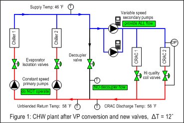
- A system with low Δ T also needs more flow to get the same cooling. The "Q x Δ T" relationship tells us that a system with a ΔT that is half of the design needs twice the water. Since pump power is proportional to the cube of the flow, twice the water requires eight times the pumping energy. Below are some measures you can take to minimize energy waste in your data center. Figure 2 gives a representation of what your data center will look like after you have taken these measures.
There are many sad stories of owners who have thought they were out of cooling capacity and spent money on new facilities when they could have simply fixed the low ΔT to unlock the capacity they paid for when the plant was built. They simply did not understand that the two basic causes of their perceived capacity limitation could be fixed relatively easily:
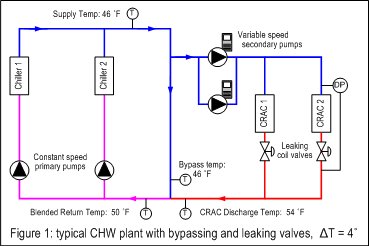
- The traditional hydronic design used in most plants requires constant chiller flow, and thus the constant generation of CHW. Any excess CHW not needed by the load flows through the decoupler line and blends with the warm water returning from the Computer Room Air Conditioner (CRAC) units. This blending reduces the return water temperature, which in turn lowers the Δ T.
- CRAC and Air Handling Unit (AHU) control valves are designed to make sure that enough water flows through the coils rather than the correct amount of water. Control valves can provide energy-efficient heat transfer only if they control the water flow in proper proportion to the quantity of heat to be rejected by the load. Leaking and/or faulty coil control valves (which are all too common) let excess cold water flow through coils, which again lowers the system's Δ T.
Increasing the maximum available cooling capacity and lowering the kW per ton thus starts with eliminating the CHW-bypassing that degrades system Δ T. Three steps are critical:
Replace leaking or faulty coil control valvesStarting with the biggest CRACs, check the entering and leaving water temperature and compare it to the specs. If the Δ T across the coil is more than two degrees below the specs, too much water is flowing and the valves should be replaced. Don't be fooled by the valve's age – a poor quality or the wrong type of valve will leak if it was installed last week! Use an industrial quality valve with high rangeability and bubble-tight shut off, and you will likely see the Δ T go above design. The hi-performance rotary valve (also known as the segmented V ball valve) offers an excellent balance between specification and price. Eliminate decoupler flow
Since CHW flows through the decoupler in most systems by design, fixing the problem requires modification of the basic hydronic model to the contemporary variable primary (VP) configuration. VP is now the preferred approach in CHW systems because of its reduced first cost (the subject of part three of this series), but its energy efficiency and impact on capacity have been the keys to its popularity in retrofitting P/S systems. Fortunately, converting most existing systems to the VP model is limited to a few mechanical modifications, including:
- Installing a modulating valve in the decoupler line.
- Installing isolation valves on the chillers.
- Installing DP transmitters across the chiller evaporators.
With the bypassing eliminated and the modulating decoupler valve installed, the primary and secondary pumps will be in series. This hydronic circuit change enables the key operational change: the variable speed secondary pumps will be solely responsible for pumping the entire CHW loop - the primary pumps are no longer used. This is a significant hydronic/operational change that obviously requires a new control sequence of operation. At the same time, it opens the door to a new adaptive control strategy designed to optimize the total plant kW per ton rather than just make enough cold water. In the new strategy, adaptive control algorithms continuously and automatically make real-time adjustments to sequence setpoints and equipment operating levels to orchestrate the efficient production of chilled water. Typical adaptive algorithms include:
- Chiller set sequencing to optimize staging/de-staging of chillers, assuring minimum chiller flow at light load conditions
- Secondary pump control to minimize total pump energy via speed regulation and sequencing to maintain valves in their most open position.
- Condenser water balancing to minimize the tower fan energy and chiller lift.
- Economizer optimization to maximize the free vs. mechanical cooling operating modes.

Summary
Chiller plants are typically underutilized and inefficient due to inherent design limitations, equipment specs and real-world operating and maintenance conditions. Most data center owners overlook the need to improve chiller plant operation when trying to minimize energy cost or new construction expense. To get all you can from your existing CHW plant, look for contributing causes of low Δ T, fix them and implement adaptive control techniques. Then watch your available tonnage go up and your kW per ton go down.
ABOUT THE AUTHOR: Mike Flaherty is general manager of tekWorx, a Cincinnati-based engineering and control firm that specializes in optimizing energy usage in chiller and boiler plants. Prior to founding tekWorx 2000, Mike had over 20 years experience in computer control and software technology for production machinery and industrial processes. He has served in executive positions at leading industrial automation companies including Allen-Bradley and Parker-Hannifin Corp.


